Centering and calibration – Automated method
The first step is to set the beam center, x-ray wavelength, and sample to detector distance. Before this can be done, you have to set the image and file header type in the Options window. The best way to find the beam center and sample to detector distance is using the automated method in RAW.
Open RAW. The install instructions contain information on installing and running RAW.
Open the Options window by going to the Options menu (top of the RAW window or in the system bar, depending on your OS) and selecting “Advanced Options”
In the options window, select the Image/Header Format section on the left.
In the area on the right, set the Image format dropdown menu to “Pilatus” and the Header file format to “G1, CHESS”.
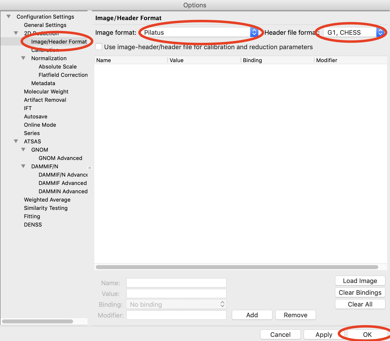
Click the OK button to close the window and save the changes to the settings.
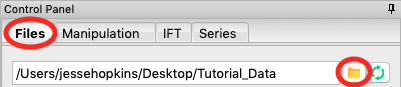
In the files tab, click on the folder button and navigate to the Tutorial_Data/calibration_data folder.
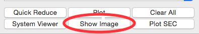
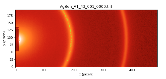
Select the AgBeh_A1_43_001_0000.tiff file by clicking on it once and click the show image button at the bottom of the screen.
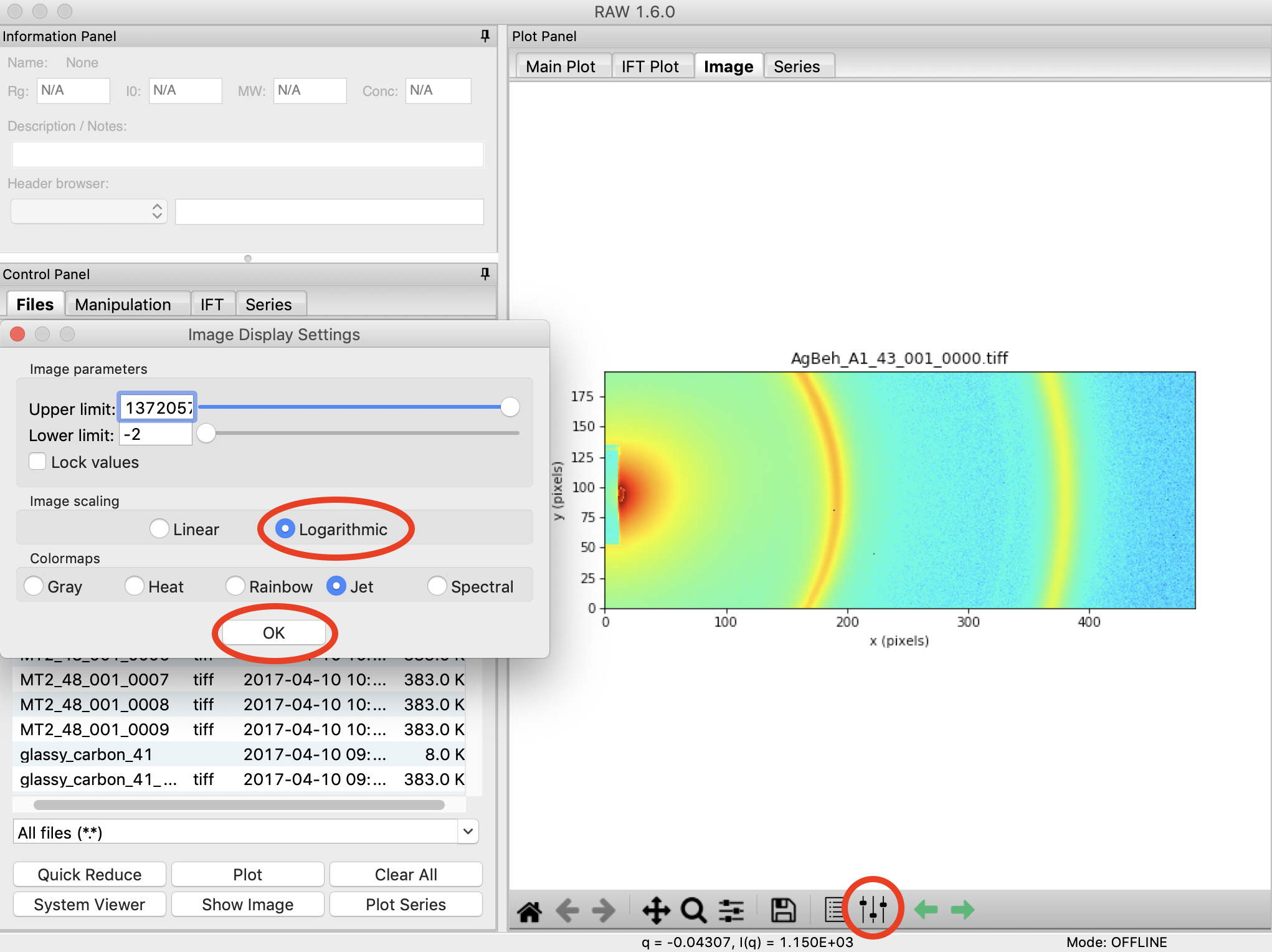
In the Image Plot Panel that is now showing, click on the Image Display Settings button (looks like slider bars) at the bottom of the screen.
In the window that appears, set the scale to logarithmic and and click “OK”.
Open the Centering/Calibration panel by going to the Tools menu and selecting “Centering/Calibration”.
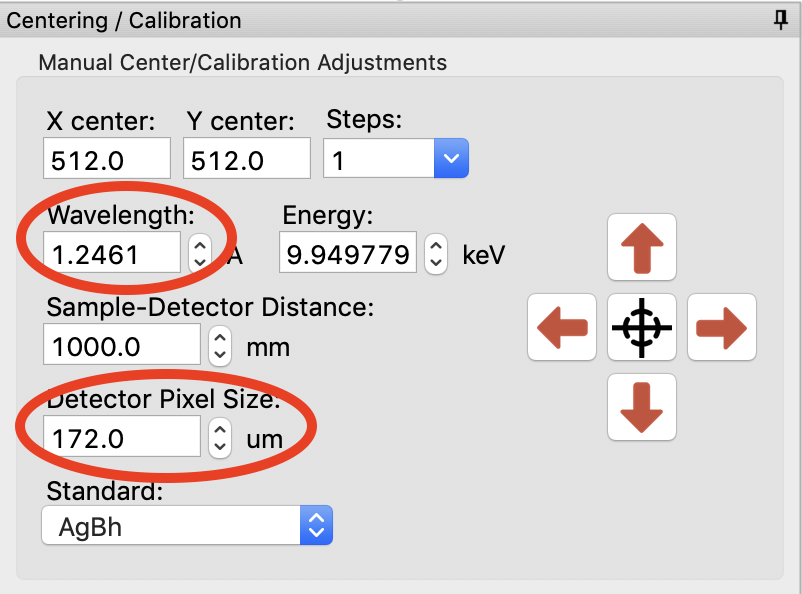
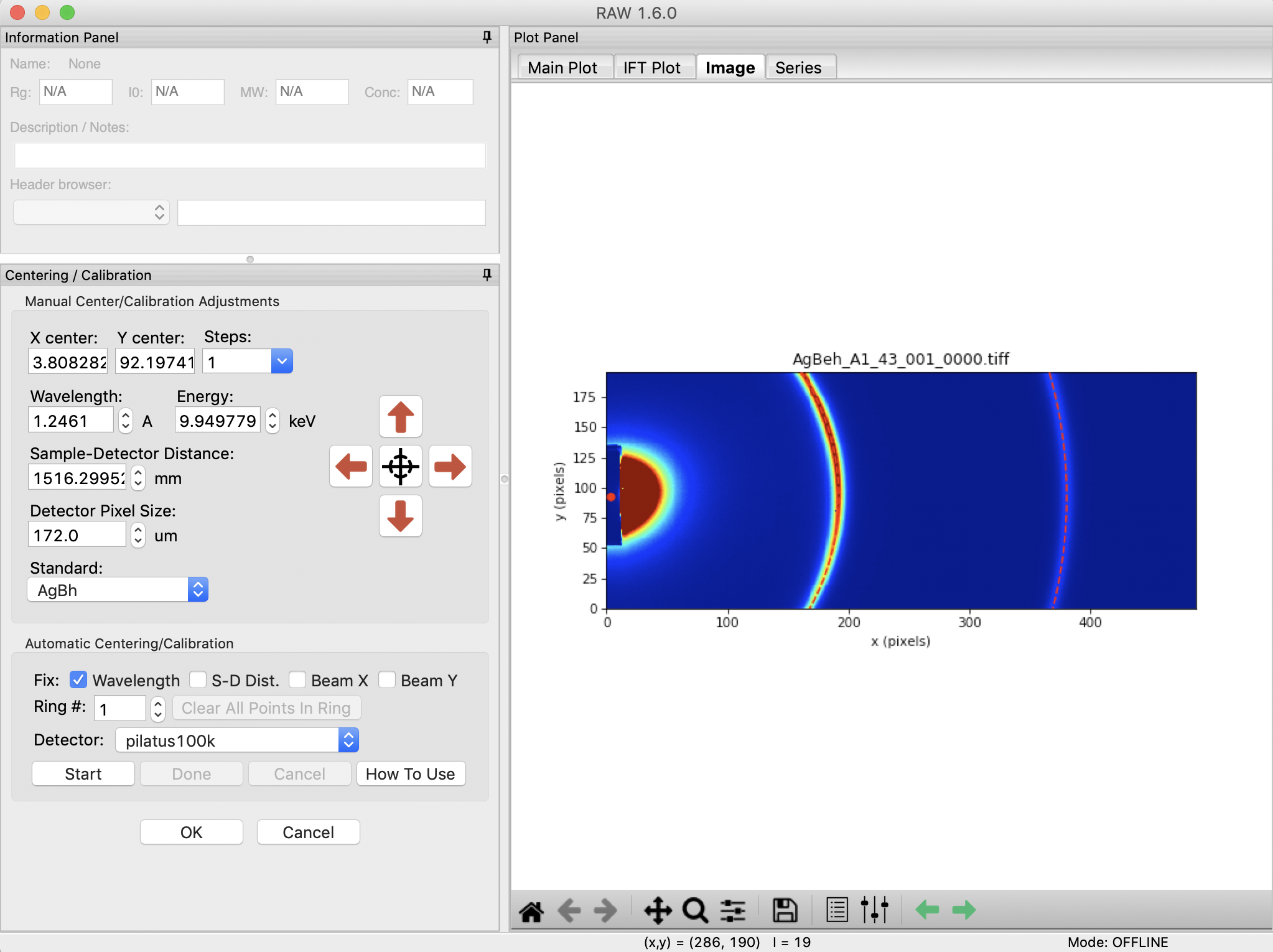
In the Centering/Calibration panel set the wavelength to 1.2461 Å. Set the detector pixel size to 172.0 μm.
- Note: The x-ray energy/wavelength and detector pixel size are previously known values, and are not found in RAW.
- Tip: You can set the value in two ways. Either using the up/down arrows next to the box (spin controls) or directly typing the value into the box.
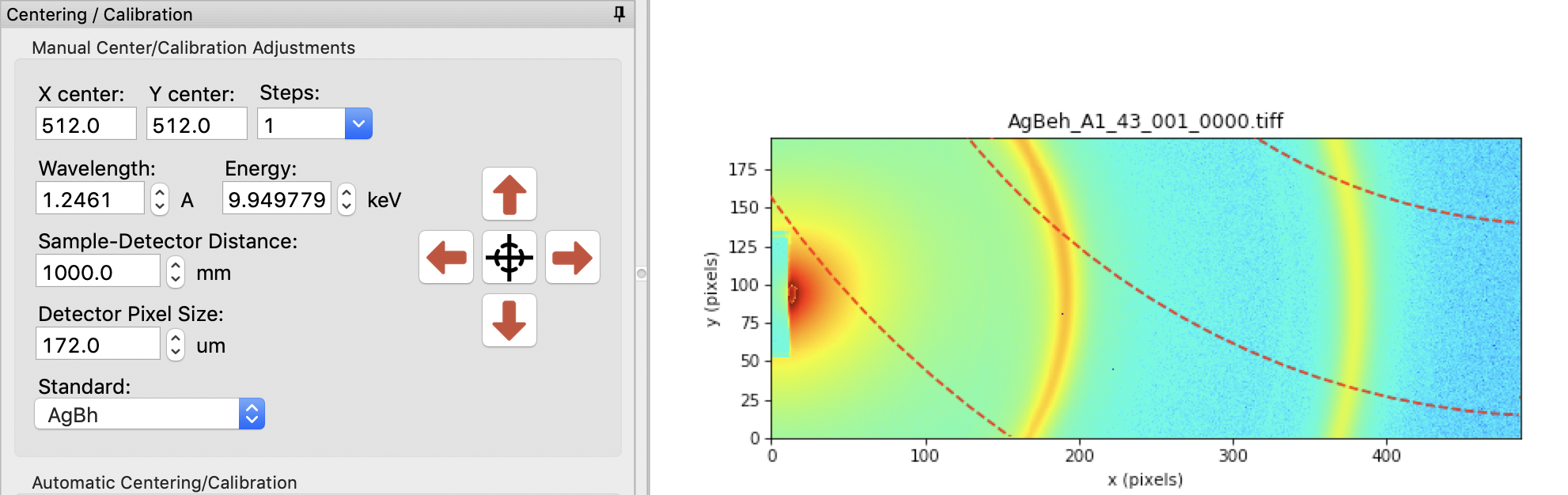
The goal of centering and calibration is to find a beam center position and sample to detector distance that causes the displayed Silver-Behenate ring pattern to match up with the rings on the image.
- Note: The beamstop is the dark blue patch extending out from the center of the left edge of the detector.
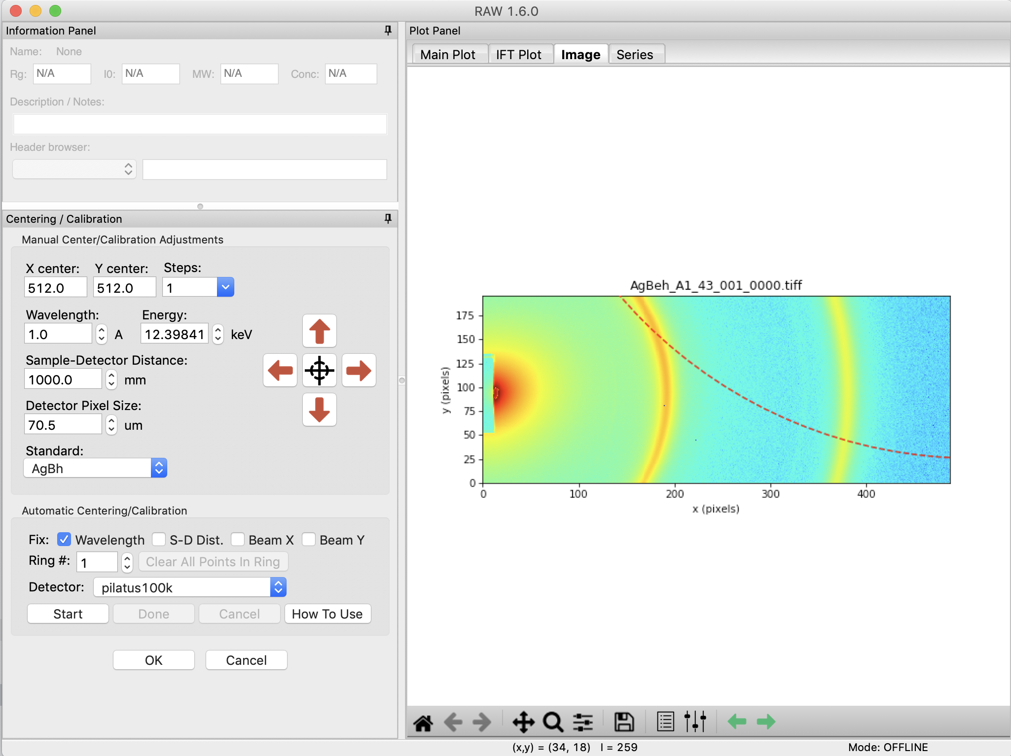
Checkpoint: You should currently have a screen that looks like the one below.
In the “Manual Centering/Calibration Adjustments” panel, make sure the correct standard is selected, in this case, AgBh (silver behenate).
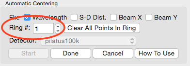
In the Automatic Centering panel, make sure the correct detector is selected, in this case “pilatus100k”.
- Note: If you cannot find your detector in that list, select “detector”, and make sure that you have entered the correct detector pixel size in the manual centering panel.
Click the “Start” button in the “Automatic Centering/Calibration” panel.
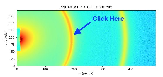
Make sure the “Ring #” is set to 0. Click on a point with strong intensity in the Silver Behenate ring nearest the beamstop (left most ring, in this case, near x = 200).
- Note: For some experimental setups, one or more of the largest d-spacing rings may not be visible on the detector. In this case, you need to figure out what the first visible ring on the detector is, and set the ring number to that. So, if the third ring was the first one on the detector, the Ring # would be set to 2 (the ring number is zero index, so 0 corresponds to the first ring, 1 to the second ring, and so on).
- Try: If you set the Manual settings to approximately right, hover the mouse above the image and use the scroll wheel to zoom out. This will let you see all of the centering rings, and figure out which ring is the first one visible on the image. Once you’re done, hit the Home button to return to the zoom of the entire image.
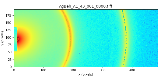
The peak intensity points in that ring will be automatically found, and labeled with yellow-green dots.
Note: If it didn’t find very many points, try clicking again on another part of the ring, and it will add more points to your selection.
Note: If you have the same ring separated by a gap (due to detector module gaps, beamstop shadow, or geometry, click on the separated parts of the rings to add points from all sections. The autofind algorithm will only find peaks in contiguous regions.
Tip: Due to the color map selected, the points may be hard to see. Try changing to the heat map to see the selected points, like in the image below.
Change the “Ring #” to 1.
Click on a peak intensity point of the second visible ring.
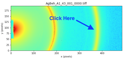
The peak intensity points in that ring will be automatically found, and labeled with blue dots.
Click the “Done” button in the “Automatic Centering/Calibration” panel and beam position, sample to detector distance, and detector pixel size will all be automatically filled in.
- Note: If the automatic centering fails, carry out Steps 5-7 of Part 2. Giving the system starting points that are approximately in the right place can help it refine to the precise location.
In the Image Display Settings, set the color scale back to Linear, and the Upper limit to 9000. You should now be able to easily see the centering rings and beam center on the image.
Click the OK button in the Centering/Calibration panel to save your settings and exit the panel.